

Copyright © 2026 A.R.I.A. Advanced Research in Audio VAT Number: 02741420240. Privacy and Cookie policy.
Unison Research choose Bludelego


A.S.H.A. Technology was developed as part of Unison Research’s ongoing commitment to innovation, with the aim of further improving audio performance while maintaining efficiency and reliability. It reflects our philosophy of combining traditional audio expertise with advanced engineering.
To achieve the highest possible audio performance while keeping power dissipation under control, we developed A.S.H.A. Technology:
Analog: Entirely based on analog design, to achieve the best possible performance.
Synchronized: The output stage relies on perfect synchronization of the power devices to nearly eliminate crossover distortion.
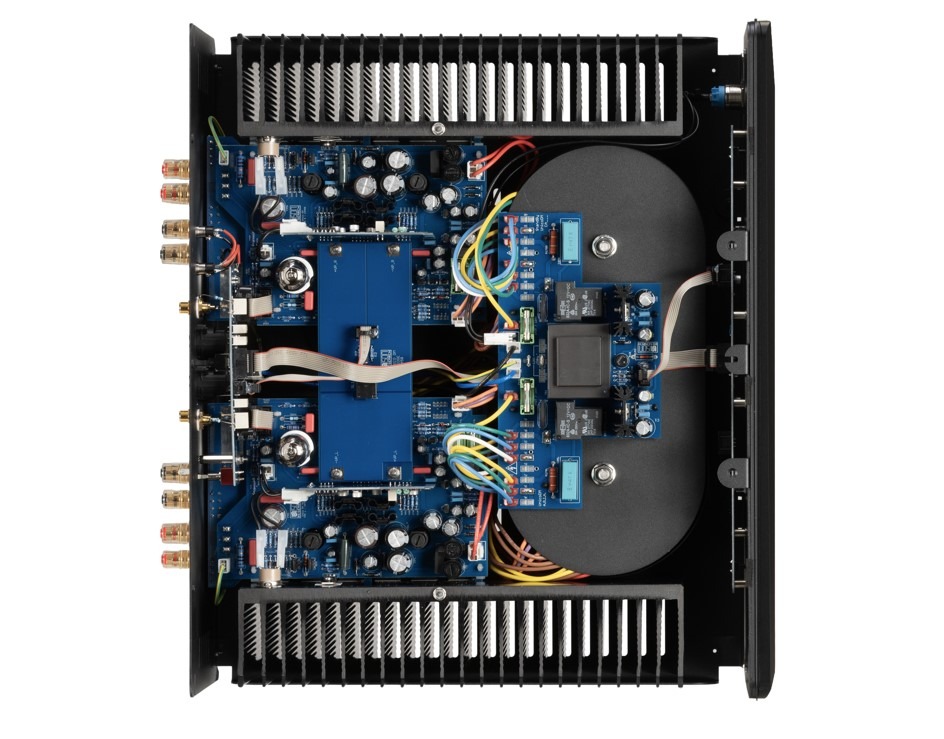
Hybrid: The design combines valves and transistors, taking advantage of the distinctive characteristics of each technology to achieve an optimal balance of musicality, linearity and power.
Amplification: All these technologies are implemented in the new power amplifier and will be used in all new Unico Line products.

Starting from the technology used in the Unico Line amplifiers, we carried out extensive research and experimentation, further improving all the aspects that were already good and addressing the remaining weaknesses.
This process led to the development of the core of A.S.H.A. Technology: an innovative power-stage configuration that we call
Technical Explanation
The output stage uses a pair of power MOSFETs in a configuration derived from the traditional push-pull topology.
A dedicated driver circuit controls the devices, which deliver the voltage and current required to drive the loudspeaker.
However, the conventional push-pull description does not fully capture how this circuit operates. The key difference lies in the way the two MOSFETs share control of the output signal and deliver current to the load.
In a conventional push-pull stage, as the name suggests, the power devices work alternately — one pushing the signal while the other pulls it.
In Class A operation, both devices conduct throughout the entire signal cycle. In Class AB, both devices conduct around the zero crossing, while their contributions become increasingly complementary as the signal amplitude increases.

In our A.S.H.A. output stage, the Leader MOSFET operates in Class A, remaining continuously active throughout the entire signal cycle. It maintains control of the output voltage at all times, while also supplying current during the positive half of the waveform. The Follower MOSFET, supports the Leader by supplying additional current during the negative portion of the waveform.
Throughout the entire signal cycle, the Leader MOSFET maintains continuous control of the output voltage. Unlike a conventional Class AB stage, there is no handover of voltage control between the two power devices at the zero crossing.
This approach virtually eliminates crossover distortion associated with the transfer of control between the output devices.
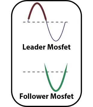
The Follower MOSFET is controlled by a dedicated circuit that monitors the current flowing through the Leader, using the voltage drop across its source resistor as a reference. Based on this measurement, the circuit adjusts the Follower’s bias to maintain the intended operating current in the Leader while providing the additional current required by the load.
We have to distinguish between two main different cases:
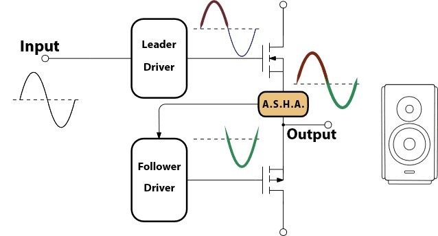
This operating principle requires precise synchronization between the two power devices. To achieve this, we developed a fast and robust control circuit that coordinates the Leader and Follower drivers, ensuring accurate current sharing and stable operation.
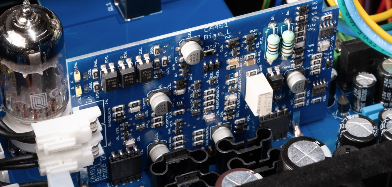
To manage this, we designed a robust and fast control circuit that integrates both drivers (one for the Leader and one for the Follower MOSFETs) using SMD technology, ensuring full circuit responsiveness and precise control.

Copyright © 2026 A.R.I.A. Advanced Research in Audio VAT Number: 02741420240. Privacy and Cookie policy.
Unison Research choose Bludelego
Click below to find a distributor or locate a store
For more commercial information, fill in the form below